For the real fun and excitement of Model Railroading build a permanent, well designed layout! Here are eight well tried and tested designs, planned by experts for your enjoyment. Choose the layout which suits your requirements – consult your dealer for the necessary track and accessories (if you own or are buying a Tri-ang Railways boxed set. remember to subtract the track units supplied from your list)-read and follow these simple instructions carefully, and discover the lasting pleasure of building and operating your own Model Railway.
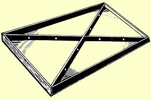
THE BASEBOARD OR TABLE This
must be firm and rigid, and as large as possible within the limitations of your
available space. It would be better to
build layout R.526. starting with just the outer
circuit and extending gradually inwards,
Before
laying track, finish the table top either by painting (matt finish) or by
TRACK ASSEMBLY Fit
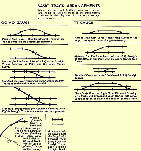
all track sections together exactly as the selected plan
PINNING DOWN
For OO/HO Series 3 and TT Type 'B- Track use standard upholsterers 3/8" black japanned gimp pins. Place all stations, high level and inclined piers, bridges, etc., in position, and test For clearance by hand running a long coach or car round the track. Use Tri-ang Railways Track Underlay (OO/HO Gauge R.200—TT Gauge T.165)under all Series 3 or Type ' B ' Track for realism and quiet running. Start under an outside section of track. Place a length of underlay (stretching it slightly) under the track and pin down track sections in sequence. Track must NOT be pinned down hard, but allowed to "float" on the underlay. Check frequently to see that straight sections really are straight, and parallel to the table edge or adjacent track where applicable. Continue pinning down, curving track underlay as necessary, until the whole layout is permanently fixed. Ensure that all points and crossings are flat and not distorted do not pin down the last section of track next to an incline.NOTE. Use Standard (grey based) Track for all inclined and high level track sections. Place a double thickness of track underlay under the last section of Series 3 Track before
an incline to compensate for difference in heights.WIRING
Instruction leaflets, which should be carefully followed, are enclosed with all electrical accessories, and special leads, complete with Contact Plugs and Tag Washers, are supplied also. Where these leads are not long enough, use a similar type of P.V.C. covered wire, together with Tri-ang Railways S.5080 Tag Washers and S.2005 Contact Plugs (available from Tri-ang Railways stockists). Make up leads to the lengths required with adequate allowance for adjustments and fitting. For neatness and efficiency all leads should run under the table except at contact points. Before commencing wiring 1/8" holes should be drilled in the table as close as possible to each contact point. Holes at various positions in table cross bracings will be found useful, as they will allow leads to pass and hold them in position Push all contact plugs firmly home in appropriate sockets on accessories, and be quite sure that the A.C. output of your power unit is used only for points and level crossings, and NEVER connected to tracks or turntable set. When wiring is completed, connect the power controller to mains supply. Check all track sections with loco operating on the track and ensure that all points and accessories are functioning correctly.NOTES.
1. All points should be wired for continuous running on each individual circuit with lever in RT.44 Lever Frame Section in forward position—reverse positions of wires in front sockets of lever frame if necessary to obtain this effect.
2. When testing circuits for correct running, ensure that all points are set for continuous running on each track circuit to prevent interaction between the various tracks. Arrange the wiring so that when the control knob is turned in a clockwise direction the locomotive goes clockwise round the track
3. On each layout the hand operated points are placed nearest to the controls for ease of operation. At any time these points may be converted to electrical operation by the addition of the appropriate point motors, wires and RT.44 Lever Frame Sections.
4. Should you plan to build a large layout (e.g. R.526) by stages, then always start with the outer circuit and plan to include all points leading to other circuits to avoid lifting the track later.
Above ALL—follow the Instruction Book
![]()